We use cookies to enhance your experience. By continuing to browse this site you agree to our use of cookies. More info.
People tend to spend, on average, several hours a day sitting on couches, chairs, and car seats, as well as considerable time on mattresses every night. Polyurethane foam plays a major role in providing comfort and support in each of these products.
Thus, it is crucial to understand how the foam is able to support extended forces and how it recovers once the person gets up. Foams undergo testing procedures to determine the ability of the foam to recover from loads and its ability to withstand repeated forces.
ASTM D3574 is one such testing method that comprises a range of tests to specify the several properties of the foam. This consists of measurements of odor, dynamic force responses, foam density, aging, and mechanical properties.
As far as mechanical testing is concerned, foams are subjected to extensive and tensile forces, and their strain and strength values are quantified.
Three compression tests, B1, B2, and C, are defined that necessitate control of a multi-segmented mechanical test. Test B1, known as the indentation force deflection test, quantifies the force that is essential to generate a few indentations present in the foam.
The forces have been reported as the indentation force deflection (IFD) values and provide information on the assistance of the foam.
Test B2, known as the indentation residual gage load test, is utilized to identify the compressed thickness of padding under the average person.
The foam’s thickness was measured under several loads and reported as the indentation residual gage load (IRGL) value.
Test C, known as the compression force deflection test, is utilized to identify the amount of force essential to produce a 50% compression more than the entire area of a sample.
This article outlines an example in which all three tests are performed on polyurethane foam.
The test configuration is displayed in Table 1. Measurements were taken on an AGS-X table-top type universal testing instrument with the help of a large circular indenter foot measuring around (200 mm diameter) and a perforated, square support plate for the samples (400 mm × 400 mm with 6.5 mm holes 20 mm apart).
The perforated support plate enables the air to escape from the foam and allows for more precise data collection. A 1 kN S-style load cell was utilized to quantify the forces on the foam. Figure 1 displays the fixtures, and Figure 2 shows the test setup.
Table 1. Equipment Configuration. Source: Shimadzu Scientific Instruments
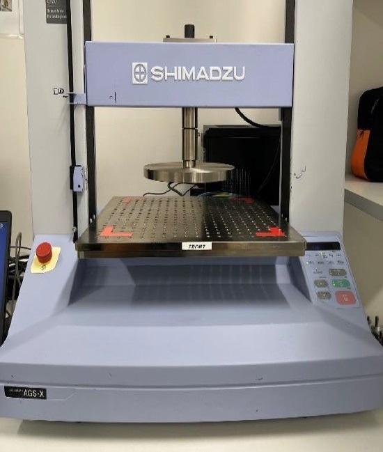
Figure. 1. Fixtures. Image Credit: Shimadzu Scientific Instruments 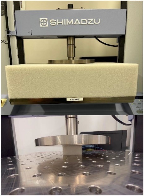
Figure 2. Test setup. Image Credit: Shimadzu Scientific Instruments
Samples used for Tests B1 and B2 consisted of dimensions of 400 mm × 400 mm with a thickness of 100 mm. Samples for Test C had dimensions of 50 mm × 50 mm with a thickness of 25 mm.
The techniques were made with the help of the Shimadzu TrapeziumX Control module, enabling users to program complicated multi-step tests to reach particular displacement or force targets.
For every test performed, the sample was pre-stressed and allowed to rest for around six minutes.
For Test B1, the sample was further stressed to 4.5 N, and the new thickness of the sample was quantified. This was utilized for the calculation of a 25% indentation and a 65% indentation. The compressions were retained for nearly 60 seconds each, and the force was quantified at the end of every 60 seconds.
As far as Test B2 was concerned, the sample was stressed to 4.5 N following the 6-minute recovery period and held at that force for 60 seconds. The sample’s thickness was quantified before moving to 110 N and 220 N, each of which was held for 60 seconds, and their strokes were quantified at the end of the waiting period.
For Test C, once the pre-stressing of the sample was done, the sample was compressed to a stress of 140 Pascals, and its new thickness was quantified. Furthermore, the sample was compressed to 50% of this new thickness and held for around 60 seconds. The stress on the sample was quantified at the end of these 60 seconds.
This particular test required three samples to be tested in the batch. Also, the average and standard deviation of their outcomes were evaluated. The force vs. stroke was plotted for every sample throughout the complete test, like the sample’s prestressing.
The outcomes are exhibited in the force versus stroke plots displayed in Figure 3 for Test B1, Figure 4 for Test B2, and Figure 5 for Test C. The dip in the force, seen in Figure 3, is a result of the foam's stress relaxation as the crosshead stroke was held for 60 seconds. The horizontal lines displayed in Figure 4 are also a result of stress relaxation present in the foam. For the latter test, the crosshead keeps on compressing the sample to maintain force, which increases the total stroke. Also, the pre-stress force versus stroke is shown in the plot.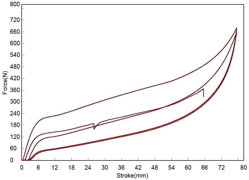
Figure 3. Force vs. stroke plots for Test B1. Image Credit: Shimadzu Scientific Instruments
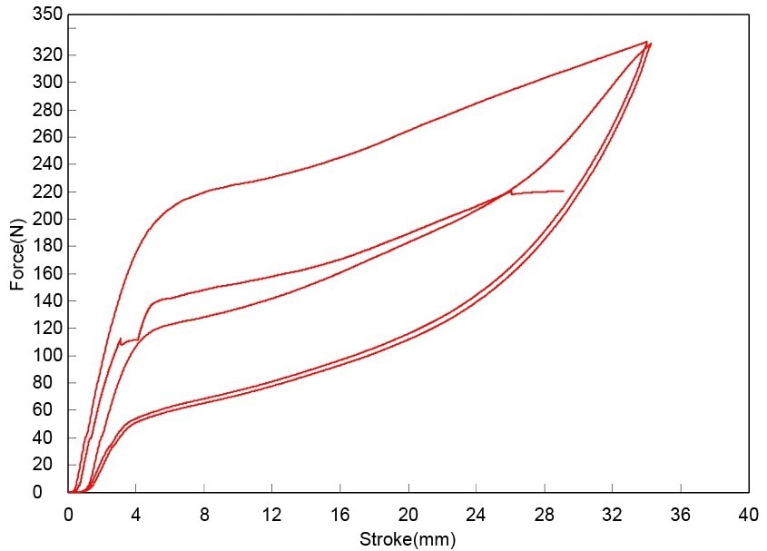
Figure 4. Force vs. stroke plots for Test B2. Image Credit: Shimadzu Scientific Instruments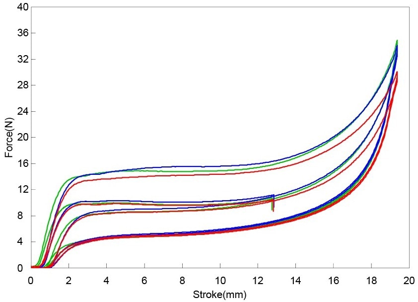
Figure 5. Force vs. stroke plots for Test C. Image Credit: Shimadzu Scientific Instruments
Table 2. IFD values, IRGL values, and the 50% compression values. Source: Shimadzu Scientific Instruments
The IFD values, IRGL values, and 50% compression values are shown in Table 2. Furthermore, the ratio of the IFD values also enabled the support factor of the foam to be determined. This value was identified to be 2.03, which is in the middle of standard support factor values for polyurethane foam.
The Shimadzu AGS-X was utilized to execute the compression tests from ASTM D3574 on polyurethane foam rubbers.
Such methods need a multi-segment test procedure that makes use of quantified data to configure additional change points and provides accurate control over the frame for a set amount of time. ASTM D3574 defines several tensile and tear tests, which could also be quantified utilizing this test frame with extra fixtures.
This information has been sourced, reviewed and adapted from materials provided by Shimadzu Scientific Instruments.
For more information on this source, please visit Shimadzu Scientific Instruments.
Please use one of the following formats to cite this article in your essay, paper or report:
APA
Shimadzu Scientific Instruments. (2023, June 05). Foam Rubber Compression Testing with ASTM D3574. AZoM. Retrieved on September 04, 2023 from https://www.azom.com/article.aspx?ArticleID=22219.
MLA
Shimadzu Scientific Instruments. "Foam Rubber Compression Testing with ASTM D3574". AZoM. 04 September 2023. <https://www.azom.com/article.aspx?ArticleID=22219>.
Chicago
Shimadzu Scientific Instruments. "Foam Rubber Compression Testing with ASTM D3574". AZoM. https://www.azom.com/article.aspx?ArticleID=22219. (accessed September 04, 2023).
Harvard
Shimadzu Scientific Instruments. 2023. Foam Rubber Compression Testing with ASTM D3574. AZoM, viewed 04 September 2023, https://www.azom.com/article.aspx?ArticleID=22219.
Do you have a question you’d like to ask regarding this article?
Cancel reply to comment
AZoM.com – An AZoNetwork Site
Owned and operated by AZoNetwork, © 2000-2023
- Call +91 8888006677 / 9422147673
- purchasesharp@gmail.com
- Wakad, Pimpri-Chinchwad, Maharashtra 411033